

 0
 0
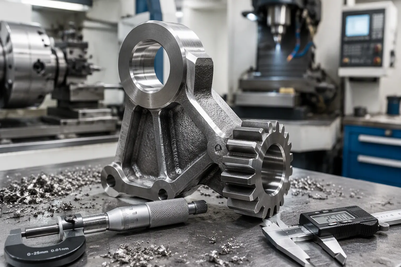
Custom forged and machined parts begin as metal shaped under compressive forging forces. Precision machining then brings them to final dimensions. This combination matters: forging aligns grain structure for strength, and machining delivers the tight tolerances and surface finishes that demanding applications require. You gain the most when you understand how process, material, design, quality, and cost decisions interlock. One question matters above all: which process combination and material will meet your application's load, precision, and volume requirements at the best total cost? This professional English B2B knowledge article of approximately 1,000 words gives you practical answers.
Key Takeaways
- Combine forging and machining to get strong parts with precise features.
- Choose materials and heat treatment early to save time and money.
- Check quality and work closely with suppliers to avoid problems.
Write a Professional English B2B Knowledge Article of Approximately 1,000 Words: Forging and Machining Explained
Forging vs. Machining at a Glance
You face two distinct starting points for a metal component. Forging shapes metal under compressive force, and machining cuts material away to create the final geometry. Each process leaves a different signature on the material.
| Property | Forging | Machining (from billet) |
|---|---|---|
| Tensile strength | 15–40% higher than equivalent casting; refined grain | Baseline (no enhancement from process) |
| Fatigue life | Excellent — refined grain, optimized grain flow | Good — depends on surface finish |
| Impact toughness | Superior — ductile, resists brittle failure | Material-dependent |
| Grain structure | Fine, refined (improved by compression) | Unchanged from raw material |
| Porosity/voids | None (consolidation via pressure) | Depends on material |
| Reliability at stress concentration | Best — grain flow optimized for load paths | Good — no material defects from process |
The table shows the trade-off clearly. Forging builds strength into the metal itself. Machining delivers geometry, features, and finish. Neither process wins everywhere. Your application decides which property matters most.
Why Combine Both Processes
You get the best result when you use each process for its strength. Forging optimizes the grain structure through controlled deformation. The metal gains superior strength, toughness, and resistance to fatigue. Forged components also exhibit enhanced load-bearing capacity. The process eliminates internal voids, porosity, and inclusions, so the metal structure stays uniform and consistent.
The mechanical gains are measurable. Forged parts show higher tensile and yield strength than machined components. They resist fatigue better under cyclic loading. They also offer improved wear resistance and greater impact toughness. Near-net forged bevel gears show 6–10 times better impact and fatigue resistance than cut gears. A cited 1997 study found forged spur gears with 12.5% higher bending fatigue strength than cut teeth.
Machining then adds what forging cannot. You get tight tolerances, complex features, and the surface finish your drawing specifies. Combine the two, and you hold strength and precision in one part.
How Forging Works
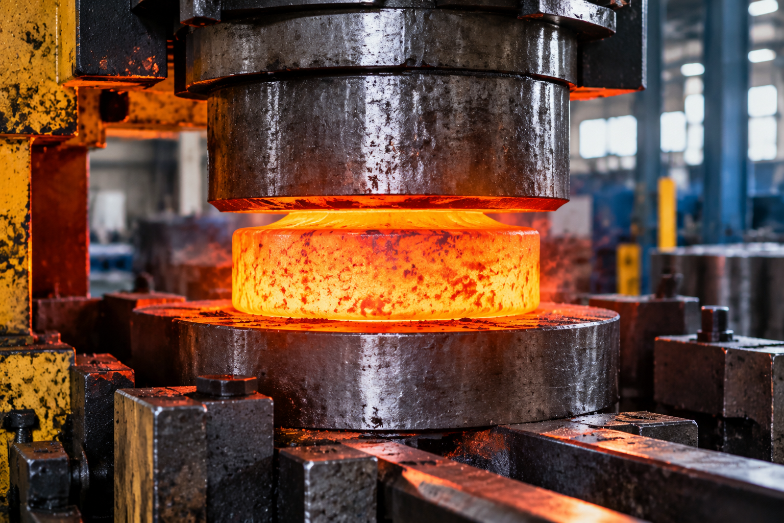
Forging shapes metal through controlled compressive force. You heat a metal workpiece and deform it between dies or presses. The deformation refines the grain structure and aligns it with the part's load paths. This process produces a component with superior strength and toughness compared to a machined part cut from a solid billet.
Types of Forging
You select a forging method based on part geometry, volume, and performance requirements. Each method suits different applications.
| Forging Method | Typical Applications |
|---|---|
| Impression die forging | Larger quantities of complex, near-net shapes; parts needing toughness, impact strength, and fatigue resistance; cost-effective with expensive alloys due to less material waste |
| Open die forging | Smaller quantities of rough shapes; very large forgings weighing many tons; simple blocks, discs, and bar lengths |
| Rolled ring forging | Ring shapes larger than about 6 inches inner diameter; precise dimensional control and contoured ID/OD configurations; wind turbines, jet engines, and gearboxes |
Open-die forging serves aerospace landing gears, oil and gas drill heads, and heavy construction machinery. Closed-die forging produces automotive gears, crankshafts, and connecting rods to high tolerances. Rolled ring forging delivers bearing rings and turbine components with precise dimensions.
Benefits of Forging
Forging builds strength into the metal itself. The process eliminates internal voids and porosity through pressure consolidation. You gain higher tensile strength, better fatigue life, and superior impact toughness. A forged part resists brittle failure under cyclic loads.
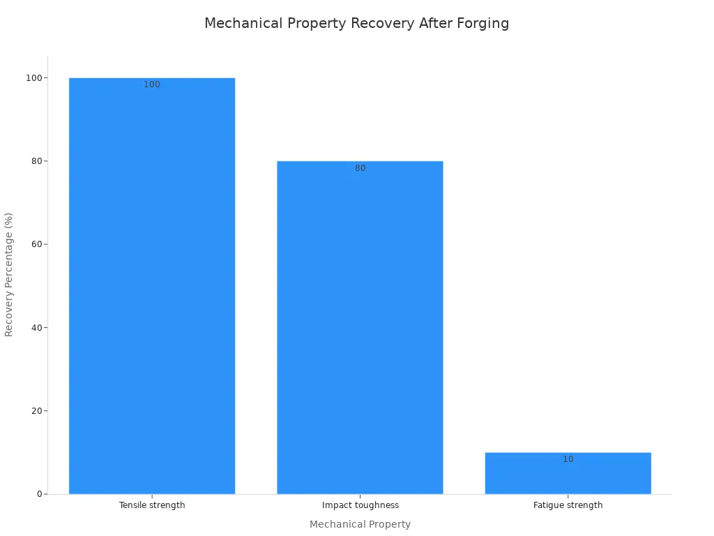
The chart shows how forging heals internal defects. Tensile strength recovers almost fully after forging. Impact toughness reaches about 80% recovery. Fatigue strength recovery demands uniform grain structure in both the joint area and the matrix. Multiple-direction deformation at high temperature promotes fine, favorably oriented grains. You get a component with reliable performance under demanding load conditions.
How Machining Complements Forging
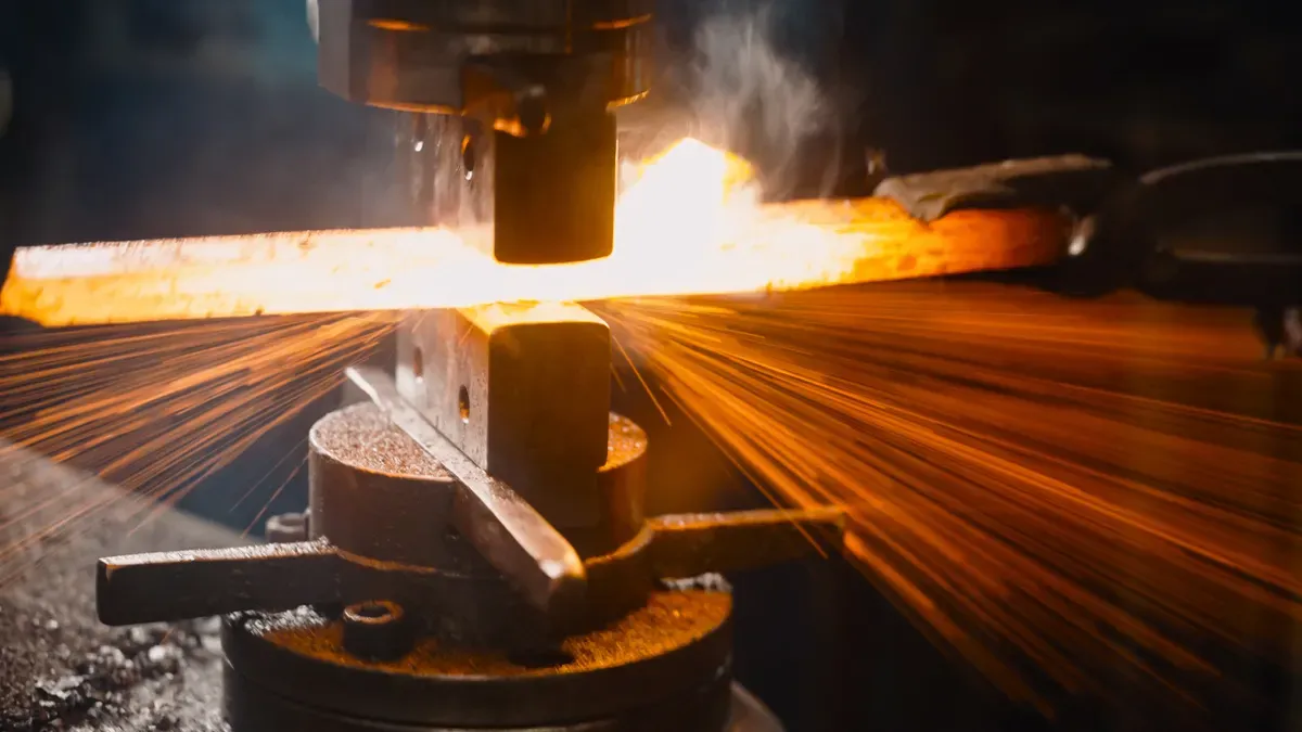
Forging gives you a strong, near-net blank. Machining turns that blank into a finished part with the exact geometry your drawing specifies. You remove the excess material left by forging and cut the features that forging cannot produce directly.
Common Machining Operations
You select operations based on the features your part needs. Most forged parts pass through several of these steps:
- Turning: You rotate the workpiece against a non-rotating cutting tool. Lathes are the principal machine tool for this operation.
- Boring: You machine the internal surface of a hole to increase its diameter. This happens by turning the workpiece on a lathe or rotating a tool in a mill.
- Drilling: You bring a rotating cutting tool axially into contact with the workpiece. You can drill on a lathe, mill, or drill press.
- Threading and tapping: You cut a defined helix into a hole or onto a shaft to fasten items together.
After roughing cuts bring the part close to final shape, you apply a finishing cut at low feed and depth. This step achieves final dimensions, tolerances, and surface finish.
Achieving Final Tolerances and Features
Machining closes the precision gap that forging leaves open. The table below shows the difference:
| Process | Typical Tolerance | Surface Finish |
|---|---|---|
| Casting | IT14–IT18 | Rough (Ra 12.5–25 μm) |
| Forging | IT13–IT16 | Medium (Ra 6.3–12.5 μm) |
| Machining | IT6–IT8 | Fine (Ra ≤1.6 μm) |
Machining forged parts allows final tolerances of IT6–IT8, which are required for gears, shafts, and precision assemblies.
You gain both strength and accuracy from this combination. Forging builds the structural base, and machining delivers the precision your application demands.
Forging vs. Machining: Strength, Precision, and Cost
You need to weigh three factors when you choose between forging and machining: strength, precision, and cost. Each factor points to a different process for different reasons. Understanding how these three forces interact helps you make a decision that serves your application over its full service life.
Strength and Grain Structure
Grain structure determines how metal carries load. Fine, well-aligned grains block crack growth and spread stress evenly. Random grain orientation creates weak boundaries where fractures begin. Forging plastically deforms the metal, so grains align with the part geometry and load direction. This alignment reduces internal discontinuities and raises fatigue performance.
When you machine a part from rolled bar or plate stock, the cutting action severs the continuous grain structure. Exposed grain boundaries act as stress concentration sites. These sites shorten fatigue life and make the part more vulnerable to corrosion cracking and stress-corrosion cracking under concentrated stresses. Forging preserves and optimizes grain flow instead. Grains run continuously along the load path, such as the longitudinal axis of a shaft. This continuous flow improves torsional strength and bending resistance.
The difference between forged and cast grain structure shows the value of controlled deformation:
| Performance Factor | Forged Grain Structure | Cast Grain Structure |
|---|---|---|
| Grain orientation | Directional, aligned with part geometry and load path | Random orientation |
| Internal integrity | Dense, minimal porosity | Higher risk of porosity |
| Fatigue resistance | High, due to continuous grain flow | Lower |
| Impact strength | Higher | Lower |
| Crack propagation | Slowed by aligned grain paths | Spreads more easily across boundaries |
| Structural reliability | Stable under cyclic loads | Less stable under repeated stress |
| Manufacturing mechanism | Plastic deformation aligns grain architecture | Solidification without alignment |
Different forging methods — closed-die, open-die, ring rolling, and precision forging — all rely on controlled plastic deformation to build strength into the internal grain architecture. Precision forging preserves grain continuity near the surface in critical stress regions. You gain a part that resists fatigue and impact from the inside out.
Precision and Surface Finish
Forging gives you strength. Machining gives you accuracy. You need both when your part must fit into a precision assembly or transmit power without vibration.
A forged blank arrives with tolerances in the IT13–IT16 range and a surface finish around Ra 6.3–12.5 μm. These values suit many structural parts. They do not suit gears, shafts, or bearing seats. Machining closes the gap. You turn, bore, drill, and tap the forged blank to reach final dimensions. A finishing cut at low feed and depth brings the part to IT6–IT8 tolerances and a surface finish of Ra ≤1.6 μm.
Machining forged parts allows final tolerances of IT6–IT8, which are required for gears, shafts, and precision assemblies.
You gain more than dimensional accuracy. Machining also creates features that forging cannot produce directly: threaded holes, keyways, oil passages, and precise tooth profiles. Each operation adds cost, so you should specify only the features your design truly needs. A generous tolerance on a non-critical surface saves machining time without harming performance.
Surface finish affects more than appearance. A smooth surface reduces friction, improves fatigue life, and limits corrosion initiation. You should match the finish specification to the contact conditions the part will face. A bearing seat needs a finer finish than a mounting flange.
Cost Drivers and Volume Considerations
Cost decisions in forged and machined parts follow a predictable pattern. Raw material dominates the total, and machining time comes second. The table below shows the typical cost breakdown for a forged and machined component:
| Cost Driver | Estimated Share |
|---|---|
| Raw material cost (at actual yield) | ~50–55% |
| Machining cost | ~20% |
| Heat treatment cost | ~12% |
| Tooling cost (amortized) | ~8% |
| Surface finishing, shot blasting, logistics | ~5% |
Raw material takes the largest share because forging consumes the most material value. Your allowance strategy — how much stock you leave for machining — directly affects both material cost and machining time. Too small an allowance risks incomplete cleanup or insufficient stock. Too large an allowance raises forging weight, machining time, tool wear, and distortion risk. A balanced allowance gives you predictable roughing and finishing. It requires reliable forging capability data from your supplier.
| Allowance Strategy | Likely Machining Effect | Main Risk |
|---|---|---|
| Too small | Less roughing and fewer chips | Incomplete cleanup or insufficient stock |
| Balanced | Predictable roughing and finishing | Requires reliable forging capability data |
| Too large | More stock removal and cycle time | Higher material use, tool wear, and distortion risk |
Volume changes the economics. CNC machining carries low tooling cost and suits prototypes and small batches. Forging carries higher upfront tooling cost, but the per-part cost drops significantly as volume increases. Medium- and high-volume OEM production favors forging for this reason.
| Factor | CNC Machining | Forging |
|---|---|---|
| Tooling cost | Low | Higher |
| Small batch cost | Better | Higher |
| Large volume cost | Higher | Better |
| Material utilization | Lower | Higher |
| Production efficiency | Moderate | High |
You should evaluate total cost, not unit price. A machined part from billet may look cheaper at low volume. At high volume, the forged and machined part usually wins on material efficiency and cycle time. The break-even point depends on part complexity, material grade, and the value of machining time saved. Ask your supplier for a cost model at your expected annual volume before you commit to a process route.
The Production Sequence: Design to Finished Part
Design and Engineering Review
You start with a structured design review. This step catches problems before tooling costs lock in. Work through these checks with your supplier:
- Select a material with proven formability, strength, and cold workability.
- Use symmetrical geometry to promote uniform material flow and avoid stress concentrations.
- Add adequate draft angles for clean ejection from the die.
- Keep fine details like threads and small undercuts within process precision limits.
- Apply fillets and radii at critical areas to improve fatigue resistance.
- Adjust tolerances and allowances for elastic recovery after deformation.
- Validate the design through prototyping and testing.
You also add flat reference surfaces for repeatable workholding. Align through-features so a single 3-axis milling pass can cut them. Run small, continuous reviews. Early corrections cost far less than late ones.
Tooling, Forging, and Heat Treatment
Your supplier builds dies, preheats them to roughly 250 °C, and synchronizes lubrication with the forging cycle. The forged blank then passes through heat treatment. Typical parameters for a carburizing-grade steel look like this:
| Step | Recommended Range | Purpose |
|---|---|---|
| Preheating | 1200–1250°F / 649–677°C | Reduce thermal shock and cracking risk |
| Austenitizing | 1795–1875°F / 980–1025°C | Form austenite and dissolve alloy carbides |
| Quenching | Air, gas, oil, or salt bath by section size | Harden the steel with controlled distortion |
| Tempering | 900–960°F / 480–515°C, double temper | Reach about 58–60 HRC with stability |
Machining and Final Inspection
Machining follows heat treatment. You turn, bore, drill, and tap the hardened blank to final dimensions. Finishing cuts bring the part to IT6–IT8 tolerances and Ra ≤1.6 μm. Final inspection then verifies every critical dimension against the drawing. You receive documented results before the part ships.
Choosing Materials and Heat Treatment
Common Metals for Forged Parts
You select a material based on load, environment, and machinability. Carbon steels suit general structural parts and offer a good strength-to-cost balance. Alloy steels add elements like chromium, nickel, and molybdenum for higher hardenability and toughness. Carburizing-grade steels such as 18Xh3a (18CrNi4A) perform well in gears and shafts that need a hard, wear-resistant surface over a tough core. Stainless steels fit corrosive environments. Aluminum and titanium alloys serve weight-sensitive applications in aerospace and marine systems. Your material choice sets the ceiling for achievable strength, so make it early.
Selecting a Heat Treatment
Heat treatment unlocks the properties your material can deliver. Four factors drive your selection: the material grade, the mechanical properties you need, the end-use conditions, and a metallurgical review of the application. Your supplier's metallurgical engineers should confirm the final recommendation.
| Application condition | Recommended heat treatment |
|---|---|
| Load capacity of gear is critical | Case hardening (first choice, despite nitriding having less distortion) |
| Low Hertzian pressures (e.g., hydraulic cylinders) with sufficient low hardness depths | Nitriding (first choice) |
| Need large hardness depths quickly, partial hardening of large parts, flexibility | Surface layer hardening |
| Large transmission components requiring highest load capacity | Case hardening (first choice) |
You also weigh hardenability, weight, dimensional changes and distortion, steel conditioning, and load capacity requirements. These factors interact. A distortion-sensitive part may favor nitriding. A heavily loaded gear usually needs case hardening. Decide the treatment before you finalize the drawing, because it shapes tolerances, stock allowance, and cost.
Quality Control and Sourcing Best Practices
Inspection Methods and Traceability
You verify quality at every stage, not just at the end. Start with non-destructive testing to catch internal and surface defects without damaging the part. Ultrasonic testing finds internal voids, cracks, and inclusions. Magnetic particle inspection reveals surface and near-surface cracks in ferromagnetic materials. Dye penetrant inspection exposes surface-breaking defects. Radiographic testing detects internal discontinuities.
Mechanical testing then confirms the material's strength, ductility, and toughness. You run tensile tests for yield strength, tensile strength, and elongation. Impact tests measure Charpy V-notch toughness at various temperatures. Hardness tests check resistance to indentation. Take specimens from representative locations so results reflect the whole lot.
Dimensional inspection closes the loop. Coordinate measuring machines (CMM) verify complex geometries. Gauges handle repetitive checks. Flatness, roundness, and straightness checks protect rotating and sealing components.
Traceability ties every part back to its raw material heat or lot. Your supplier should provide a complete quality dossier with each shipment:
| Document | Purpose |
|---|---|
| Material certificates (EN10204 3.1) | Confirm chemical composition and mechanical properties |
| Heat treatment records | Document thermal process parameters |
| Dimensional inspection reports | Verify conformance to drawing |
| NDT reports (UT/MT) | Record defect detection results |
| Mechanical testing results | Confirm strength and toughness |
Check that the heat lot on the mill certificate matches the lot on the certificate of conformance and the inspection records. Outside-processing certificates must reference the same lot. This chain most often breaks at special-process handoffs, where material certs, heat numbers, and lot travelers must survive transfer to a vendor's systems and back.
Common Pitfalls and Supplier Collaboration
Several pitfalls recur in forged and machined part sourcing. Tolerance stack-up ranks among the most consistent and preventable. It arises when you assign tolerances across features and stages without accounting for how they interact. Simulate tolerance propagation before your supplier cuts tooling.
Material selection is another recurring issue. Tradeoffs made in isolation at the design stage cause downstream consequences. Treat material choice as a lifecycle decision, not a one-time pick.
Fragmented supply chains introduce hidden costs. Setup and tooling misalignment, scrap and rework risk, logistics complexity, and quality escapes can eclipse low unit prices. Evaluate total cost of ownership rather than quoted price.
Supplier collaboration addresses these pitfalls. An end-to-end, lifecycle-owned engineering model gives you cross-stage visibility. You catch variation before machining adds cost. Near-net-shape forming reduces material removal and scrap. Early alignment of forming and finishing stages preserves repeatability as volume scales.
Choose suppliers who offer batch numbering, material traceability, and full documentation. Verify material test certificates and supplier sourcing. Confirm the supplier follows strict quality checks and precision forging techniques. Partner only with certified suppliers (ISO, ASTM, IATF) to avoid compliance risk. Select suppliers who act as partners, offering process improvements, better materials, and cost-saving techniques.
Match the process to your application. Choose forging for strength and material efficiency. Choose machining for precision and complex features. Select material and heat treatment early, because both drive performance and cost. Verify quality control and documentation before production begins. Involve suppliers during design review to capture cost and quality gains.
FAQ
When should you choose forging over machining?
Choose forging when your part carries heavy loads or cyclic stress. Choose machining when your design needs tight tolerances and complex features. Most demanding applications benefit from both processes combined.
Why should you finalize material and heat treatment before tooling?
Material and heat treatment set achievable strength, hardness, and distortion limits. They also drive stock allowance and cost. Locking them early prevents expensive redesign after dies and fixtures exist.
How do you verify supplier quality before production?
Request material certificates, heat treatment records, and inspection reports for sample lots. Confirm the heat numbers match across all documents. Audit the supplier's certifications and traceability chain first.
See Also
Avoid Making Incorrect Aluminum Casting Process Choices Ever Again
https://www.xuxiangtaimetal.com
Qingdao Xuxiangtai Machinery